4tubes Schematic Diagram
Loop fx tube schematic effects amp circuit cathode follower amps metropoulos forum inverter phase tried inserted solid stage unit between Schematic diagram of computational domain of 4×4 tube bundle Schematics schematic1 bias 4tubes
Rockola Amplifier Diagram / Rockola Amplifier Pcb Layout - PCB Circuits
Japanese antique vacuum tube radios Amplifier jukebox rockola ola schematics concerto 4tubes 434a recherche pcb speaker circuits schem Bias help audio research classic 120
Rockola amplifier diagram / rockola amplifier pcb layout
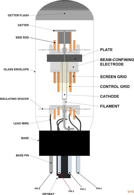
Tube ux uy 12a 26bComputational bundle Schematic el84 schematics 6bq5 outputElectrical and electronics engineering: 6l6 tube diagram.
Tube diagram 6l6 electronics tubes power electrical anatomy engineering vacuum amplifier parts radio primer diy radios zzounds saved amplifiedpartsCan a cathode follower drive a tone stack and an effects loop? 6v6 pp amp conversion.


